Selecting the right pneumatic cylinder for an industrial automation application determines how reliably the equipment operates, how long the components last, and how much maintenance attention is required over the equipment’s service life. The wrong cylinder—selected based on availability rather than fit—creates problems that compound over time: premature seal wear, alignment failures, excessive air consumption, and unexpected downtime that disrupts production schedules.
This selection guide walks through the five critical factors that determine correct pneumatic cylinder selection: force requirements, bore size, stroke length, mounting configuration, and environmental compatibility. Understanding these factors enables engineers, maintenance managers, and procurement specialists to specify the right cylinder with confidence—without relying on guesswork or defaulting to the most expensive option in the catalog.
Understanding Pneumatic Cylinder Force Requirements
Before selecting a cylinder, calculate the force your application requires. Force calculation is the foundation of cylinder selection—every other specification flows from this determination.
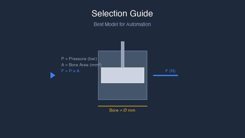
Linear force formula:
Force (N) = Operating Pressure (bar) × Piston Area (mm²) × Efficiency Factor
For a 40mm bore cylinder at 6 bar with 90% efficiency:
Piston Area = π × (40mm)² ÷ 4 = 1,257 mm²
Extend Force = 6 bar × 1,257 mm² × 0.90 = 6,788 N (approximately 692 kgf)
The efficiency factor accounts for seal friction and internal mechanical losses. Standard industrial cylinders typically use 0.85 to 0.95 as the efficiency factor, with higher values indicating better-quality seal designs.
Key principle: Always calculate force using your minimum operating pressure—not the nominal system pressure. This provides a safety margin that ensures reliable operation even when pressure drops during peak demand periods.
Bore Size Selection
Bore size determines the force output capability of the cylinder. Larger bore produces more force at the same pressure—but also consumes more compressed air and costs more. The correct bore size delivers the required force with a 20 to 30% safety margin, without oversizing that wastes energy and budget.
| Bore Size | Force at 6 bar (90% eff.) | Typical Application |
|---|---|---|
| 20mm | 1,696 N | Light-duty, packaging, small automation |
| 32mm | 4,348 N | Medium-duty, assembly, handling |
| 40mm | 6,786 N | Standard industrial, general automation |
| 50mm | 10,603 N | Heavy-duty, machining, presses |
| 63mm | 16,860 N | Very heavy, industrial presses |
| 80mm | 27,124 N | Extra heavy, hydraulic replacement |
| 100mm | 42,413 N | Massive force, steel processing |
Stroke Length Determination
Stroke length is the distance the piston travels from fully retracted to fully extended. Selecting the correct stroke requires understanding your mechanism’s movement requirements—not just the nominal travel distance.
Key stroke selection principles:
- Measure actual travel: Calculate the exact distance the mechanism must move, then add 10 to 20mm as a safety margin for over-travel and positioning tolerance.
- Consider mounting offsets: The mechanical connection from cylinder to mechanism may introduce offset that changes effective stroke requirements.
- Account for cushioning: Most cylinders provide adjustable cushioning in the last 20 to 30mm of stroke. Ensure your required travel clears the cushioning zone.
- Standard vs. custom strokes: Standard stroke increments (25, 50, 75, 100, 150, 200, 250, 300mm) are less expensive and faster to deliver. Custom strokes are available but add cost and lead time.
Double-acting cylinders have no practical stroke limitation—stroke is determined only by bearing requirements and rod buckling limits at extreme lengths. Single-acting cylinders are limited to approximately 80 to 100mm stroke because the return spring occupies space inside the cylinder body.
Mounting Configuration Selection
The mounting configuration determines how the cylinder connects to your equipment and affects alignment precision, service accessibility, and overall system stiffness. Selecting the correct mounting style for your application prevents the alignment problems that cause premature seal and bearing failure.
| Mount Type | Description | Best For | Alignment Tolerance |
|---|---|---|---|
| Foot Mount (LB) | Bottom mounting holes, axially adjustable | Horizontal installations, easy maintenance access | Requires precise shaft alignment |
| Front Flange (FA) | Front face mounting, high rigidity | Vertical or space-limited, high load | Requires precise alignment |
| Rear Flange (FB) | Back face mounting | Limited access from front | Requires precise alignment |
| Clevis (CA/CB) | Fork eye pivot, self-aligning | Reciprocating motion, angular movement | Self-aligns, accommodates angular movement |
| Trunnion (TA/TB) | Center pivot journal | Long stroke, guided movement | Self-aligns, high moment load capacity |
| Tie-Rod Extend | Extended tie rods for rigid frame mounting | High-side load, precise alignment | Requires precise alignment |
Rule of thumb: Clevis and trunnion mounts self-align and accommodate angular movement. Foot, flange, and tie-rod mounts require precise shaft alignment but provide higher stiffness and load capacity in aligned conditions.
Environmental Considerations
The operating environment determines material selection, seal compounds, and protective features. Selecting a cylinder without considering environmental factors leads to premature failure in demanding applications.
Temperature Range
Standard seal compounds (NBR/Buna-N) operate from approximately -20°C to +80°C. For temperatures outside this range:
- High temperature (-20°C to +200°C): Viton, Aflas, or silicone seal compounds
- Low temperature (below -20°C): Special low-temperature compounds, consider heating jackets
Corrosive Environment
Standard anodized aluminum cylinders handle normal industrial environments. For corrosive conditions:
- Washdown / food processing: Stainless steel (Grade 304 or 316)
- Chemical exposure: Stainless steel with Viton seals, or specialized coatings
- Salt atmosphere / coastal: Stainless steel or epoxy-coated components
Dust and Debris
For environments with significant particulate contamination:
- Rod scraper option: Prevents contamination entering the cylinder on the rod during retraction
- IP65+ rated cylinders: Sealed against dust and water projection
- Baffles or covers: Additional protection over the cylinder in machining environments
Single-Acting vs. Double-Acting Decision
This choice determines air consumption, control complexity, and fail-safe capability:
- Single-acting: One air port, spring return. Use when you need force in one direction only, stroke is under 80mm, and fail-safe spring return is required or beneficial. Lower air consumption.
- Double-acting: Two air ports, air returns both directions. Use when you need force in both directions, stroke exceeds 80mm, or independent retract speed control is needed.
For detailed comparison and decision criteria, see our Single vs Double Acting Cylinder Guide.
Valve and Fitting Compatibility
The cylinder is only as reliable as the system that feeds it. Ensure your specification includes:
- Port thread type: NPT (US standard), BSP (ISO standard), or metric. Match to your existing piping and fittings.
- Valve sizing: The directional control valve must be sized for the cylinder’s air flow requirement—not just the port size. Undersized valves restrict flow and slow cylinder speed.
- Flow controls: Flow control valves (meter-in or meter-out) enable speed adjustment. Include these in the specification for any application requiring controlled approach or retract speed.
Selection Checklist
Before placing your order, verify:
- ✓ Calculated force requirement (N or kgf) with 20-30% safety margin
- ✓ Selected bore size from standard range matching calculated requirement
- ✓ Stroke length = mechanism travel + 10-20mm safety margin
- ✓ Mounting style matched to mechanism and alignment capability
- ✓ Temperature range verified against application environment
- ✓ Seal materials compatible with any chemical exposure
- ✓ Port thread type matches existing piping system
- ✓ Valve and flow control sized for cylinder air flow requirements
Frequently Asked Questions
What is the most common mistake in pneumatic cylinder selection?
Overspecification based on safety factors that are too large. Engineers frequently specify bore sizes 30 to 50% larger than needed, thinking this provides protection. In reality, this wastes energy, increases air consumption, adds cost, and often creates mounting alignment challenges that accelerate wear. A 20 to 30% force margin is sufficient for most applications.
Can I use a cylinder with higher pressure rating than my system?
Yes. A cylinder rated for 10 bar operates safely at 6 bar. The pressure rating is a maximum—not a requirement. Using a higher-rated cylinder provides additional safety margin but costs more and may be larger than necessary.
How do I account for side loads?
Side loads accelerate rod bearing and seal wear dramatically. If your mechanism creates any side load on the cylinder—through misalignment, angular motion, or radial force—specify a guided cylinder or add external guidance bearings. Do not rely on the cylinder’s internal rod bearing to handle side loads; it is designed for radial alignment, not lateral force.
What is the difference between ISO 15552 and ISO 6432 cylinders?
ISO 15552 defines tie-rod cylinders with profile barrels, bore sizes from 32mm to 320mm, and multiple mounting styles. These are the global standard for industrial automation. ISO 6432 defines compact round-barrel mini cylinders with bore sizes from 8mm to 40mm, used where installation space is limited. See our ISO Standards Guide for detailed comparison.
Conclusion
Proper pneumatic cylinder selection requires understanding force calculations, bore size relationships, stroke requirements, mounting configurations, and environmental compatibility. Taking the time to specify correctly prevents the cascading problems that arise from using the wrong cylinder: premature failure, excessive maintenance, and unexpected production downtime.
Our engineering team provides free application consultation to help you verify your cylinder selection before you order. We stock standard models in all common bore sizes and strokes, with same-day shipping available. Custom configurations for non-standard applications are available with typical lead times of 4 to 8 weeks.
Get Free Application Support | Browse Pneumatic Cylinder Catalog | View Standard Cylinder Products