Choosing the correct air cylinder for an industrial automation application determines how reliably the equipment operates, how efficiently it uses compressed air, and how often maintenance is required over the equipment’s service life. A well-selected cylinder delivers the required force and stroke while lasting millions of cycles without intervention. A poorly selected cylinder—chosen based on what is in stock rather than what the application requires—creates cascading problems: premature seal wear, unexpected downtime, and inflated maintenance costs.
This step-by-step guide walks through the complete air cylinder selection process, from force calculation through environmental compatibility, with practical decision criteria at each stage. Use this guide to select cylinders with confidence for any industrial automation application.
Step 1: Calculate Your Force Requirements
Before opening a product catalog, determine how much force your application actually needs. Force calculation is the foundation of correct cylinder selection—every other specification follows from this calculation.
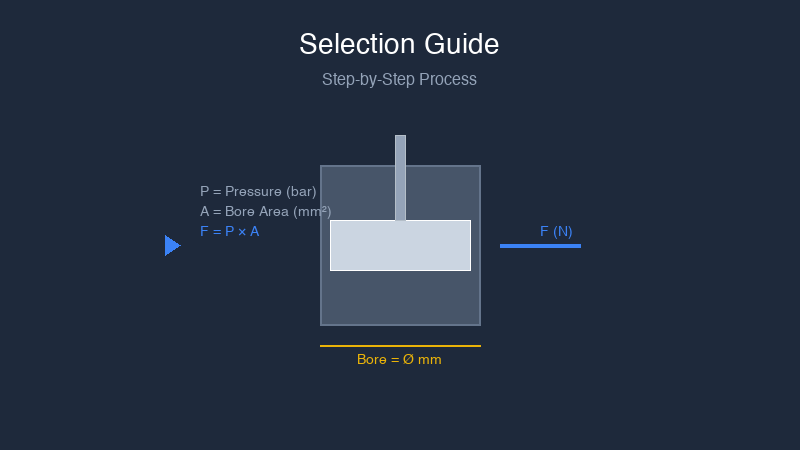
The force formula:
Force (N) = Operating Pressure (bar) × Piston Area (mm²) × Efficiency
Where:
- Operating Pressure: Your system’s working pressure (typically 4-6 bar for standard pneumatic systems). Always use your minimum operating pressure, not the nominal setpoint.
- Piston Area: Calculated from bore size: π × (bore/2)²
- Efficiency: Typically 0.85-0.95 for standard cylinders, accounting for seal friction and internal mechanical losses
Example calculation for a 40mm bore cylinder at 5 bar with 90% efficiency:
Piston Area = π × (40mm)² ÷ 4 = 1,257 mm²
Force = 5 × 1,257 × 0.90 = 5,655 N (approximately 577 kgf)
Critical principle: Always calculate using your minimum operating pressure—not nominal pressure. This ensures the cylinder performs reliably even when pressure drops during peak demand.
Step 2: Select the Appropriate Bore Size
Bore size determines the force output of the cylinder. Larger bore = more force, but also more air consumption and higher cost. The correct bore delivers the required force with a 20-30% safety margin, without oversizing.
| Bore Size | Force at 5 bar (90% eff.) | Typical Application |
|---|---|---|
| 20mm | 1,414 N | Light-duty, packaging, small automation |
| 32mm | 3,623 N | Medium-duty, assembly, handling |
| 40mm | 5,655 N | Standard industrial, general automation |
| 50mm | 8,836 N | Heavy-duty, machining, presses |
| 63mm | 14,047 N | Very heavy, industrial presses |
| 80mm | 22,640 N | Extra heavy, hydraulic replacement |
Rule of thumb: When in doubt, round up one bore size. The marginal cost increase of the next bore size is small compared to the reliability benefit of having adequate force margin.
Step 3: Determine the Required Stroke Length
Stroke length is the distance the piston travels from fully retracted to fully extended. Select stroke based on your mechanism’s actual movement requirement—not a catalog default.
Stroke selection guidelines:
- Measure exact travel: Calculate the precise distance the mechanism must move, then add 10-20mm as a safety margin for over-travel and positioning tolerance.
- Consider mounting offsets: The mechanical connection from cylinder to mechanism may introduce offset that changes effective stroke requirements.
- Account for cushioning: Most cylinders provide adjustable cushioning in the last 20-30mm of stroke. Ensure your required travel clears the cushioning zone.
- Standard vs custom: Standard stroke increments (25, 50, 75, 100, 150, 200mm) are less expensive and faster to deliver. Custom strokes are available for non-standard requirements.
Step 4: Choose the Correct Mounting Style
Mounting configuration affects how the cylinder integrates into your equipment and determines the alignment precision required. Selecting the correct mounting style prevents the alignment problems that cause premature seal and bearing failure.
| Mount Type | Best For | Alignment Requirement |
|---|---|---|
| Foot Mount (LB) | Horizontal installations, easy maintenance | Requires precise shaft alignment |
| Front Flange (FA) | Vertical or space-limited applications | Requires precise alignment |
| Clevis (CA/CB) | Reciprocating motion, angular movement | Self-aligning, accommodates angular movement |
| Trunnion (TA/TB) | Long stroke, guided movement | Self-aligning, high moment load capacity |
Key principle: Clevis and trunnion mounts self-align. Foot, flange, and tie-rod mounts require precise shaft alignment but provide higher stiffness and load capacity when properly installed.
Step 5: Evaluate Operating Environment
The operating environment determines material selection, seal compounds, and protective features. A cylinder specified without considering environmental factors fails prematurely in demanding applications.
Temperature Considerations
- Standard seals (-20°C to +80°C): NBR/Buna-N compounds for general industrial use
- High temperature (to +200°C): Viton or silicone seal compounds
- Low temperature (below -20°C): Special low-temperature compounds
Corrosive Environments
- Washdown / food processing: Stainless steel construction (Grade 304 or 316)
- Chemical exposure: Stainless steel with appropriate seal compounds
- Dust and debris: IP65+ rated cylinders with rod scraper options
Step 6: Single-Acting vs. Double-Acting Decision
The choice between single and double-acting configuration determines air consumption, control complexity, and fail-safe capability:
- Single-acting: One air port, spring return. Use when force is needed in one direction only, stroke is under 80mm, and fail-safe spring return is required. Lower air consumption.
- Double-acting: Two air ports, air returns both directions. Use when force is needed in both directions, stroke exceeds 80mm, or independent retract speed control is needed.
Selection Checklist
Before placing your order, verify:
- ✓ Calculated force requirement with 20-30% safety margin
- ✓ Selected bore size matching calculated requirement
- ✓ Stroke length = mechanism travel + 10-20mm margin
- ✓ Mounting style matched to mechanism requirements
- ✓ Temperature and environmental compatibility confirmed
- ✓ Port thread type matches existing piping
- ✓ Valve and flow control sized for cylinder requirements
Frequently Asked Questions
What is the most common selection mistake?
Oversizing the bore for unnecessary safety margin. This wastes energy, increases air consumption, and adds cost without corresponding benefit. A 20-30% force margin is sufficient for most applications.
How do I account for side loads?
Side loads accelerate rod bearing and seal wear dramatically. If your mechanism creates any side load, specify a guided cylinder or add external guidance bearings. Do not rely on the cylinder’s internal rod bearing to handle lateral force.
What if my application requires non-standard specifications?
Custom cylinder configurations are available for applications requiring non-standard bore, stroke, mounting, or environmental ratings. Working with a manufacturer that provides custom engineering support ensures correct specification for specialized requirements.
Conclusion
Proper air cylinder selection requires understanding force calculations, bore size relationships, stroke requirements, mounting configurations, and environmental compatibility. Taking the time to specify correctly prevents premature failure and unexpected downtime.
Our engineering team provides free application consultation to help you verify your cylinder selection. We stock standard models with same-day shipping and offer custom configurations for specialized requirements.
Get Free Application Support | Browse Cylinder Catalog | View Standard Products