Calculating the force of a pneumatic cylinder is straightforward — on paper. But real-world factors like friction, pressure drops, and load angles quietly reduce what you actually get. This guide covers the formulas, the charts, and the practical adjustments that turn theory into a reliable specification.
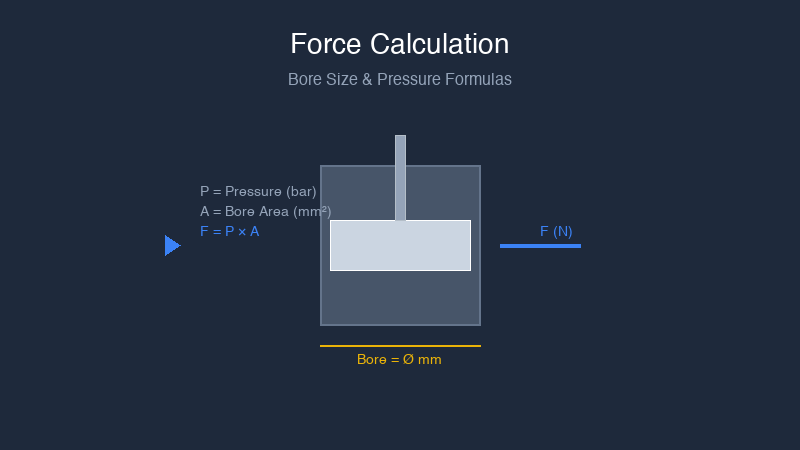
The Basic Formula
The theoretical force of a pneumatic cylinder is:
F = P × A
Where:
- F = Force (Newtons)
- P = Gauge pressure (Pascals)
- A = Effective piston area (m²)
In more practical units:
F = P × A / 10
Where:
- F = Force (N)
- P = Pressure (bar)
- A = Area (mm²)
And in imperial:
F = P × A
Where:
- F = Force (lbf)
- P = Pressure (psi)
- A = Area (in²)
Piston Area by Stroke Direction
Extension (Push) Force
On extension, the full piston face is exposed to pressure:
A_extend = π × (D / 2)²
Where D = bore diameter.
Retraction (Pull) Force
On retraction, the rod occupies part of the piston area:
A_retract = π × (D / 2)² − π × (d / 2)²
Where d = rod diameter.
Example Calculation
A 50mm bore cylinder with a 20mm rod, operating at 6 bar:
Extend force:
A = π × (50/2)² = π × 625 = 1,963 mm²
F = 6 × 1,963 / 10 = 1,178 N ≈ 120 kg-force
Retract force:
A = π × (50/2)² − π × (20/2)²
  = 1,963 − 314 = 1,649 mm²
F = 6 × 1,649 / 10 = 990 N ≈ 101 kg-force
Force Charts at Common Pressures
Extend Force (N) by Bore Size and Pressure
| Bore (mm) | 4 bar | 6 bar | 8 bar | 10 bar |
|---|---|---|---|---|
| 20 | 126 | 188 | 251 | 314 |
| 25 | 196 | 295 | 393 | 491 |
| 32 | 322 | 482 | 643 | 804 |
| 40 | 503 | 754 | 1,005 | 1,257 |
| 50 | 785 | 1,178 | 1,571 | 1,963 |
| 63 | 1,247 | 1,870 | 2,493 | 3,117 |
| 80 | 2,011 | 3,016 | 4,021 | 5,027 |
| 100 | 3,142 | 4,712 | 6,283 | 7,854 |
| 125 | 4,909 | 7,363 | 9,817 | 12,272 |
| 160 | 8,042 | 12,064 | 16,085 | 20,106 |
Retract Force (N) — Standard Rod Sizes at 6 bar
| Bore (mm) | Rod (mm) | Retract Force (N) |
|---|---|---|
| 20 | 10 | 141 |
| 25 | 12 | 227 |
| 32 | 12 | 415 |
| 40 | 16 | 633 |
| 50 | 20 | 990 |
| 63 | 20 | 1,681 |
| 80 | 25 | 2,722 |
| 100 | 30 | 4,288 |
Real-World Adjustments
Theoretical force is rarely what you get. Apply these factors:
Friction Loss (Multiply by 0.85–0.95)
Seal friction consumes 5–15% of theoretical force, depending on seal type and condition. New cylinders with polyurethane seals are at the higher end; worn-in cylinders with low-friction seals are at the lower end.
Recommended: Multiply theoretical force by 0.90 as a default friction allowance.
Pressure Drop (Factor by Application)
The pressure at the cylinder port is lower than at the regulator, especially during high-speed cycling. Tubing length, bends, fittings, and valve flow all contribute.
Recommended: Assume 0.5–1 bar loss for typical installations. Use 5 bar for calculations even if your regulator reads 6 bar.
Safety Factor (Multiply Force Requirement, Not Capacity)
Never spec a cylinder that delivers exactly the force you calculated. Add margin:
| Application Type | Recommended Safety Factor |
|---|---|
| Horizontal, low-friction load | 1.25x |
| Vertical lift | 1.5x |
| High-friction or sticky load | 1.5–2.0x |
| Clamping (force matters, not speed) | 1.5x |
| Unknown or variable load | 2.0x |
Load Angle Correction
If the cylinder pushes at an angle to the direction of motion, you lose effective force:
F_effective = F_cylinder × cos(θ)
Where θ is the angle between the rod axis and the load direction. A 15° misalignment loses about 3.4% of force. A 30° misalignment loses 13.4%.
Rod Buckling: The Stroke Limit
For long-stroke cylinders under compressive load, the rod can buckle before the cylinder reaches its pressure rating. Euler's formula gives the critical buckling load:
F_critical = π² × E × I / (K × L)²
Where:
- E = Modulus of elasticity (steel ≈ 210,000 MPa)
- I = Area moment of inertia of the rod = π × d⁴ / 64
- K = End-fixity factor (1.0 for pinned-pinned, 0.7 for pinned-fixed, 0.5 for fixed-fixed)
- L = Unsupported rod length (stroke + allowances)
Simplified Buckling Check
For a steel rod with a pinned-pinned end condition:
| Rod Diameter (mm) | Max Stroke at 500 N Load (mm) | Max Stroke at 1,000 N Load (mm) |
|---|---|---|
| 10 | 410 | 290 |
| 12 | 590 | 417 |
| 16 | 1,050 | 740 |
| 20 | 1,640 | 1,160 |
| 25 | 2,560 | 1,810 |
| 30 | 3,690 | 2,610 |
If stroke exceeds these values at your expected load: increase rod diameter, use a guided cylinder, or add an external guide that unloads the rod.
Quick Online Calculator Approach
The manual calculations above are good for understanding, but for day-to-day work, use the force calculator on our website. Enter your bore, pressure, and stroke, and it handles friction, pressure loss, and buckling checks automatically.
Practical Specification Example
Given:
- Horizontal cart on linear rails, weight 80 kg
- Friction coefficient: 0.1 (ball-bearing rails)
- Required stroke: 600 mm
- Operating pressure: 6 bar
- Push only (spring return or gravity return on retract)
Step 1 — Force to move the load:
F_load = 80 kg × 9.81 m/s² × 0.1 = 78.5 N
Step 2 — Apply safety factor (1.5×):
F_required = 78.5 × 1.5 = 118 N
Step 3 — Account for friction loss (÷ 0.90):
F_cylinder = 118 / 0.90 = 131 N
Step 4 — Select bore from chart (6 bar):
A 25mm bore produces 295 N extend force → adequate.
Step 5 — Check buckling:
At 25mm bore, rod is typically 12mm. At 600mm stroke and 118 N load, well under the 417 N buckling limit at 1,000mm. Safe.
Result: 25mm bore double-acting cylinder, 600mm stroke.
At Air Cylinder Manufacturing, we provide detailed force data, CAD models, and engineering support to help you spec the right cylinder. Use our online force calculator, or send us your load case and we'll do the math.
Try our force calculator or contact our engineers.
Calculate your cylinder requirements: Online Force Calculator | Standard Cylinder Specifications