A well-specified cylinder installed poorly will fail early — often catastrophically. Misalignment is the single biggest killer of pneumatic cylinders, causing rod bending, seal wear, and bore scoring. Getting the installation right from the start saves money, downtime, and frustration.
1. Before You Mount: Pre-Installation Checks
Before bolting anything down, verify:
- Cylinder matches the spec: Bore, stroke, mounting type, and cushioning are correct per the BOM.
- Rod is clean and undamaged: Even minor scratches will destroy seals.
- Ports are clean: Blow out any debris with clean, dry compressed air.
- Air supply is conditioned: FRL unit is installed and functional (filtered to 5 microns or better).
- Mounting surface is flat and rigid: A warped mounting plate transfers stress into the cylinder body.
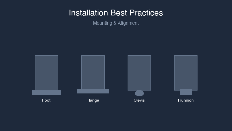
2. Mounting Types and When to Use Each
| Mount Type | Load Direction | Critical Alignment Check |
|---|---|---|
| Foot mount | Axial (along rod axis) | Rod axis must be parallel to load path |
| Front flange | Axial | Flange face must be square to rod axis |
| Rear flange | Axial | Flange face must be square to rod axis |
| Trunnion | Swiveling | Trunnion pins must be perpendicular to rod axis |
| Clevis | Swiveling | Clevis pin parallel to pivot axis |
| Rod-end eye / spherical bearing | Articulating | Rod-end threads fully engaged with lock nut tight |
Critical rule: The cylinder body should never absorb side loads or bending moments. If the load applies force at an angle to the rod axis, add an external linear guides or use a guided cylinder.
3. Alignment: The Make-or-Break Step
For Fixed (Non-Swiveling) Mounts
- Mount the cylinder loosely — hand-tighten all bolts.
- Extend the rod fully (at low pressure).
- Check alignment between the rod end and the load attachment point:
- Use a straightedge along the rod axis
- Use feeler gauges to check for gaps at the load coupling
- Maximum permissible misalignment is typically 0.05mm per 100mm of stroke
- Shim the mounting surface if needed to correct angular misalignment.
- Torque mounting bolts to specification only after alignment is verified.
- Re-check alignment after torqueing — bolt tightening can shift the cylinder.
For Pivoting (Trunnion / Clevis) Mounts
- Ensure the trunnion axis is exactly perpendicular to the rod centerline.
- Verify the cylinder swings freely through its full arc without binding.
- Check that the rod-end connection also articulates freely — two pivoting joints in series can bind if not aligned in parallel planes.
4. Port Connections and Tubing
Undersized tubing starves the cylinder of flow and kills cycle speed.
| Cylinder Bore | Recommended Tube OD | Minimum Port Size |
|---|---|---|
| Up to 25mm | 6mm | M5 or 1/8" |
| 32–50mm | 8mm | 1/8" or 1/4" |
| 63–100mm | 10–12mm | 1/4" or 3/8" |
| 125mm+ | 12–16mm | 3/8" or 1/2" |
Rules:
- Keep tubing runs as short as possible. Every meter of tubing adds volume that must be pressurized and exhausted each cycle.
- Avoid sharp bends that restrict flow.
- Use the same tubing diameter on both extend and retract ports.
5. Speed Control: Flow Control Valves
Speed is controlled by metering the exhaust, not the inlet. Install flow control valves so they restrict flow out of the cylinder:
- Connect the flow control directly to the cylinder port (or as close as possible)
- The check valve should allow free flow into the cylinder
- The needle valve restricts flow out of the cylinder
For horizontal cylinders with light loads, meter the exhaust on both ports. This gives smooth, controlled motion in both directions.
For vertical cylinders lowering a load, install a flow control that meters the exhaust from the bottom port. Without metered exhaust, the load can free-fall.
6. Cushion Adjustment
If your cylinder has adjustable pneumatic cushioning:
- Start with the cushion needle valve fully closed, then open 1–2 turns.
- Cycle the cylinder at operating speed.
- Close the cushion valve gradually until you hear a soft stop (no metallic impact).
- Do not close the valve completely — this can create a hydraulic lock effect that prevents the piston from reaching end of stroke.
- Adjust both end caps independently — they rarely need identical settings.
7. Sensor Installation
For magnetic piston sensors (reed or solid-state):
- Mount the sensor in the cylinder's sensor groove.
- Slide the sensor to the approximate trip position.
- Connect the sensor to its load (PLC input or relay).
- Cycle the cylinder slowly and watch the LED indicator.
- Fine-tune the position until the sensor triggers reliably at the desired point.
- Tighten the sensor mounting screw — but not excessively; overtightening cracks the sensor housing.
For solid-state sensors (PNP/NPN): Wire polarity matters. Double-check the wiring diagram before powering up.
8. Commissioning: Start-Up Sequence
After installation is complete:
- Set regulator to minimum pressure (1–2 bar).
- Manually cycle the directional valve (if pilot-operated, use the manual override).
- Observe the first few cycles at low pressure — watch for binding, rubbing, or jerky motion.
- Listen for air leaks at all fittings and cylinder ports.
- Gradually increase pressure to operating level.
- Adjust flow controls to achieve the desired cycle speed.
- Adjust cushion needle valves for soft deceleration at both ends.
- Run at least 20 cycles at full speed and pressure. Check:
- Mounting bolts remain tight
- No new leaks have appeared
- Cycle speed is consistent
- Cushion impact is soft and consistent
- Record baseline: cycle time, operating pressure, and flow control settings. This is your reference for future troubleshooting.
Common Installation Mistakes
| Mistake | Consequence |
|---|---|
| Side-loading the rod | Premature seal and bearing failure |
| Overspec'd tubing runs | Slow cycle times |
| Forgetting the exhaust flow control | Uncontrolled speed in one direction |
| Cushion too loose or too tight | Hard impacts or incomplete stroke |
| Pinched sensor cables | Intermittent position signals |
| Mounting on an uneven surface | Cylinder body distortion, rod binding |
At Air Cylinder Manufacturing, every cylinder ships with a detailed mounting guide specific to that model. Need installation support? Our applications engineers can walk you through it.
Get installation support — phone or email support available.
Installation essentials: Pneumatic Tubing & Fittings | Get Installation Support